Author: Paul LeBeau. Cave Rock Software Ltd. 26 May 2013
The treatment of auto orientation markers in the various SVG renderers is inconsistent and the implementations tend to be buggy.
The aim of this document is to show the problem and propose some clarifications to the SVG specification that will remove any confusion as to how to correctly render vertex markers - especially "auto" markers.
The following test file demonstrates some of the bugs and inconsistencies.
<?xml version="1.0" standalone="no"?>
<!DOCTYPE svg PUBLIC "-//W3C//DTD SVG 1.1//EN" "http://www.w3.org/Graphics/SVG/1.1/DTD/svg11.dtd">
<svg width="16cm" height="6cm" viewBox="0 0 1600 600" version="1.1"
     xmlns="http://www.w3.org/2000/svg">

  <defs>
    <marker id="Start"
      viewBox="0 0 10 10" refX="0" refY="5"
      markerUnits="strokeWidth"
      markerWidth="4" markerHeight="3"
      orient="auto"
      fill="green">
      <path d="M 0 0 L 10 5 L 0 10 z" />
    </marker>
    <marker id="Mid"
      viewBox="0 0 10 10" refX="0" refY="5"
      markerUnits="strokeWidth"
      markerWidth="4" markerHeight="3"
      orient="auto"
      fill="orange">
      <path d="M 0 0 L 10 5 L 0 10 z" />
    </marker>
    <marker id="Stop"
      viewBox="0 0 10 10" refX="0" refY="5"
      markerUnits="strokeWidth"
      markerWidth="4" markerHeight="3"
      orient="auto"
      fill="red">
      <path d="M 0 0 L 10 5 L 0 10 z" />
    </marker>
  </defs>

  <rect x="2" y="2" width="1596" height="596"
        fill="none" stroke="blue" stroke-width="4" />

  <g marker-start="url(#Start)" marker-mid="url(#Mid)" marker-end="url(#Stop)"
     fill="none" stroke="black" stroke-width="20">

    <path transform="translate(100, 100)"
          d="M 300 0 L 400 0 400 0 400 400 300 400 M 300 200 L 100 300 100 100 Z"/>

    <path transform="translate(600, 100)"
          d="M 300 0 L 400 0 400 0 400 0 400 400 300 400 M 300 200 L 100 300 100 100 300 200 Z"/>

    <polygon transform="translate(1100,100)"
          points="100,100, 300,200, 100,300"/>

    <line transform="translate(1300,500)" x1="0" y1="0" x2="0" y2="0"/>
    <polyline transform="translate(1400, 500)" points="0,0"/>
  </g>
</svg>
The file tests the following potential edge cases:

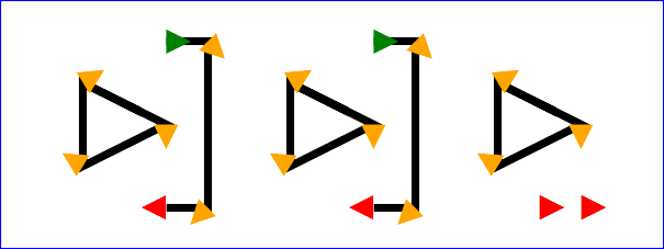
The following images show how this file is rendered by various implementations.
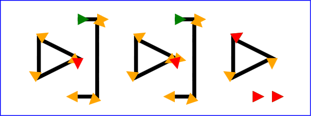
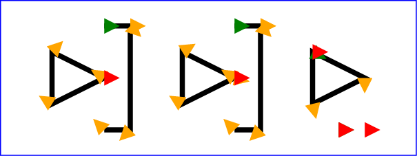
IE does not properly render markerUnit="strokeWidth" markers.
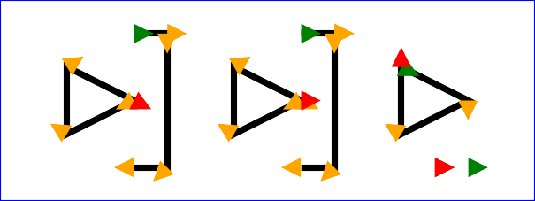
It is hard to say what is a "correct" rendering based on the SVG 1.1 spec because it does not describe how all of these cases should be correctly handled. However my opinion of what an ideal (SVG2) rendering ought to look like is as follows.
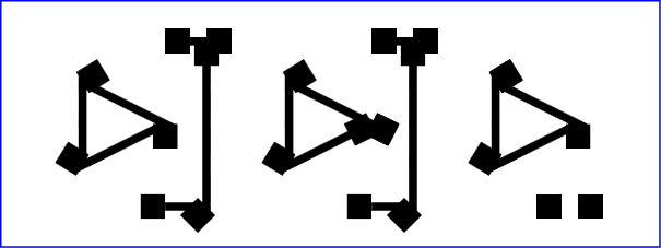
Handling of polylines and polygons is also inconsistent. The following image shows three squares composed using (from left to right) a 'rect', a 'polyline' and a 'polygon'.
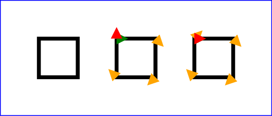

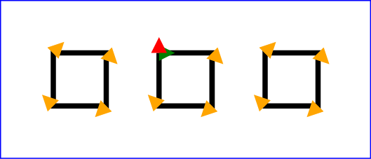
SVG 1.1 does not include 'rect' in the list of markable elements. Why was this? I propose that the markable element definition be expanded to include 'rect'. Also 'rect' and 'polygon' should be treated as if they are closed paths. So the "correct" rendering of this file ought to be be as follows.
A value of ‘auto’ indicates that the marker is oriented such that its positive x-axis is pointing in the direction of the path at the point it is placed.
If the marker is a vertex marker, then the direction the marker is oriented is, if considering the incoming and outgoing directions as unit vectors, in the direction of the sum of these two vectors. If this sum is zero, then the marker is oriented in the incoming direction.
If there are two or more consecutive points in a path that coincide exactly (both their x and y values are the same) then all the consecutive coinciding points should be treated as if they were a single vertex.
If the marker is on the first vertex of a closed subpath, then the outgoing direction is taken from the first path segment and the incoming direction is taken from:
A value of ‘auto-start’ behaves exactly the same as ‘auto’ except for the treatment of the start marker. If the subpath is an open subpath, then the start marker is positioned so that it points in the exact opposite direction (inverse vector) to the first path segment.
For ‘polygon’ elements, the last vertex is the same as the first vertex, and for ‘path’ elements that end with a closed subpath, the last vertex is the same as the first vertex of that final subpath. In this case, if the value of ‘marker-end’ is not none, then it is possible that two markers will be rendered on that final vertex.
with:For 'path' elements, closed and open subpaths are treated differently.
For open subpaths, the first vertex of a subpath should be considered a start vertex. The last vertex should be considered an end vertex. All other vertexes should be considered mid vertexes. If the subpath is degenerate — that is, it consists solely of a move, or it has only two points and both the start and end points coincide — render an end marker and orient it so that it is parallel to the effective tangent at that subpath's point. See ‘path’ element implementation notes for details on how to determine the tangent of a zero-length subpath.
For closed subpaths, all vertexes should be considered mid vertexes. No start or end markers should be rendered on that subpath. If the first and last point of a closed subpath coincide, only one marker should be rendered at that point.
Any consecutive duplicated vertexes in a path - either open or closed - should be treated as if they were a single vertex.
Treat 'line' and 'polyline' elements as if they were an open subpath.
Treat 'rect' and 'polygon' elements as if they were a closed subpath.